
What Are Jigs and Fixtures? Roles in Manufacturing and Assembly
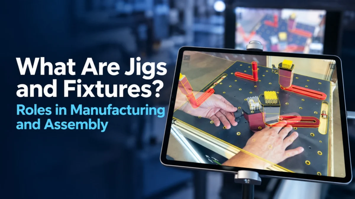
Jigs and fixtures are tools that hold, locate, and guide parts during machining, welding, assembly, or inspection. A jig guides the cutting or drilling tool, while a fixture holds the workpiece in a defined position. Both help production teams perform repeatable operations by providing a defined physical reference for part placement and process execution. In assembly and welding, fixture setup verification is an important step. SuPAR App can support this process by overlaying the CAD reference and defined inspection checkpoints onto the physical fixture for AR-guided visual verification.
What are jigs and fixtures in manufacturing?
In manufacturing, a jig is a device that controls the path or position of a tool relative to a workpiece. A fixture is a device that securely holds a part in a known location while an operation is performed. The two terms are often used together, and many tools combine both functions. Jigs and fixtures reduce the dependence on operator judgment by providing a repeatable reference for every part. They are common in machining, welding, drilling, assembly, and checking operations across automotive, transportation, aerospace, and heavy industry.
What are the main components of a jig and fixture?
Most jigs and fixtures share a set of basic components. A base or plate provides the foundation and mounts the tool to the machine table or assembly bench. Locators define the part position, typically using pins, blocks, or nests that establish the reference points. Clamps hold the part in place during the operation. Guide elements, such as bushings in a drilling jig, direct the tool. Supporting features may include handles, stops, and sensors that confirm the part is loaded correctly. The arrangement of these components determines how accurately and consistently the part can be placed each time.
What types of jigs and fixtures are used in production?
Jigs and fixtures are classified by their function and by the operation they support. Drilling jigs guide drill bits to the correct hole positions. Milling fixtures hold parts during cutting operations. Welding fixtures hold components in position while they are joined, often with integrated clamps and reference points. Assembly fixtures bring multiple parts together in the correct relationship, and checking fixtures are used to confirm that a finished part or sub-assembly is in its expected state. Each type is designed around the part geometry, the process, and the required level of repeatability.
How are welding jigs and fixtures used?
Welding jigs and fixtures hold components in their intended positions while they are welded. They control distortion by clamping the parts firmly and by accommodating the heat generated during welding. In welded structures, such as chassis, frames, and steel assemblies, the fixture often defines the position of studs, brackets, and other attachments. Operators load the parts, confirm the clamp status, and then perform the weld sequence. Visually verifying that expected components are present and appear in their intended locations before welding can help identify setup issues earlier and reduce the risk of rework later in the process.
How are jigs and fixtures designed?
Design typically begins with the part drawing or 3D CAD model and a clear definition of the operation the tool must support. Engineers identify the datum features that will locate the part, decide how clamping forces will be applied without distorting the part, and plan access for the operator and the process tool. Material selection, rigidity, and maintenance requirements are also considered. Once a concept is developed, the design is reviewed against the production volume, cycle time, and expected changes to the part. Many teams use CAD models of the fixture and the part together to check clearances and confirm the layout before manufacturing the tool.
What should be checked before a fixture goes into production?
Before a fixture is released to production, teams usually confirm that it locates the part correctly, that clamps engage as intended, and that the tool is free from interference with the process. A visual comparison of the fixture with its CAD reference can help verify that expected components are present and visually located in the intended areas, and that no defined element is missing. Documentation is also important, including the fixture identification, revision status, and any setup instructions. Verification steps should be defined in advance so that every fixture is checked the same way before it is used on the shop floor.
How can AR support fixture assembly and verification?
Augmented reality can support fixture assembly by showing the CAD reference of the fixture over the physical structure while the team builds or checks it. Inspection checkpoints for components such as locators, clamps, and supports can be prepared in SuPAR Composer and delivered through SuPAR App, helping operators visually verify whether each expected element is present and appears in its intended location relative to the CAD reference. This can help operators identify missing or additional elements during setup and document inspection findings in a digital record. AR verification is a visual aid and does not replace the mechanical design, clamping analysis, or the physical checks required by the production process.
Frequently Asked Questions
What materials are jigs and fixtures made from?
Jigs and fixtures are commonly made from steel, aluminium, or cast iron, depending on the load, the required rigidity, and the expected service life. Hardened steel is often used for locators and bushings that wear. Lighter materials may be selected for handling tools where weight matters. The choice depends on the process and the production environment.
How is a production fixture different from a checking fixture?
A production fixture holds a part during a manufacturing operation, such as machining, welding, or assembly. A checking fixture holds a finished part or sub-assembly so that its features can be compared with the design requirements. Both use locating and clamping principles, but a checking fixture is designed to support visual or functional verification rather than the production process itself.
How often should production fixtures be re-checked?
The frequency depends on usage, the process, and the quality requirements of the plant. Teams often set a schedule based on production hours, cycle counts, or observed wear. Fixtures used in high-volume welding or machining may require more frequent checks than those used occasionally. The schedule should be defined in the plant’s quality procedures.
Can one fixture be used for several part variants?
Some fixtures are designed with adjustable or modular locators that accommodate more than one variant of a part. This approach can reduce tooling cost, but it requires careful design so that each variant is positioned correctly and cannot be loaded in the wrong configuration. Where variants differ significantly, separate fixtures are usually safer.
Who is responsible for fixture verification in a plant?
Responsibility is usually shared between manufacturing engineering, which owns the fixture design and setup, and quality engineering, which defines the verification requirements. Operators and supervisors carry out routine checks on the shop floor. The exact allocation of responsibilities should be documented in the plant’s quality system.