
Checking Fixture Inspection with Augmented Reality
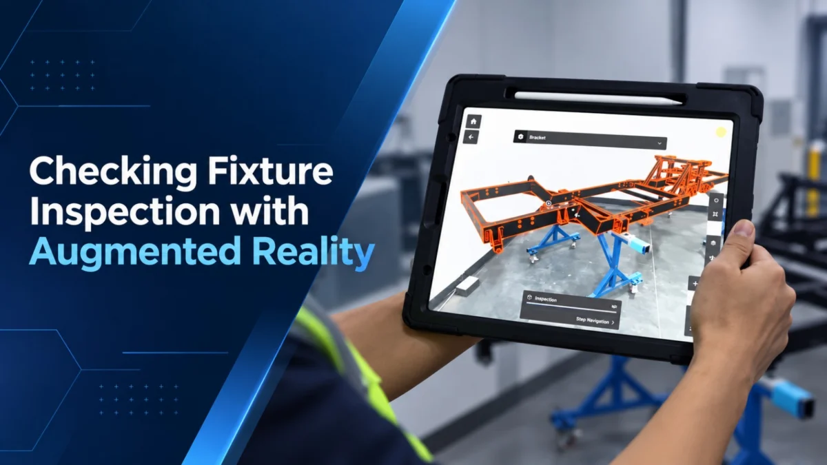
Checking fixture inspection with augmented reality is the verification of a fixture’s own build and setup by overlaying its CAD data onto the physical fixture, so that the intended configuration and the actual configuration are visible at the same time. Instead of reading a fixture drawing alongside the hardware, the operator sees nominal geometry and defined checkpoints positioned on the clamps, pins, and locators themselves.
This matters because a checking fixture is a reference, and a reference in an unknown state produces conclusions in an unknown state. The part checks that follow are only as reliable as the fixture configuration behind them.
What is a checking fixture?
A checking fixture, sometimes called an inspection fixture or a checking aid, is a purpose built tool that holds a manufactured part in a defined, repeatable position so its features can be compared against the intended design. It is common in automotive and sheet metal production, where parts are flexible, produced in volume, and checked frequently.
Most checking fixtures share a common set of elements:
- Base plate. The structural reference the rest of the fixture is built on.
- Locators and pins. Features that establish part position against its datum scheme.
- Clamps. Devices that hold the part in the located position without deforming it.
- Datum blocks and pads. Surfaces that define the reference planes.
- Gauges and probes. Elements that present specific features for checking.
- Variant hardware. Interchangeable components used when one fixture serves several part versions.
Each of these is a discrete, geometry defined element that is either visually present in the expected location or not. That is precisely the class of question AR-based visual inspection is suited to, and it is why fixture inspection is one of the more natural entry points for augmented reality in a plant.
How are checking fixtures used in production?
Checking fixtures sit at the points where a part changes hands. A supplier uses one before shipping. A receiving plant uses one during incoming inspection. A press shop uses one after a die change. A body shop uses one to confirm a subassembly before it moves on.
The appeal is speed. An operator loads the part, clamps it, and works through defined inspection features directly at the line using the fixture as the reference. That speed is the reason fixtures are reconfigured often, moved between cells, and rebuilt for new variants.
Each of those events can change the fixture. The part check itself is quick, but fixture configurations may change between formal calibration events due to rebuilds, variant changes, relocation, or maintenance activities. That gap is where AR-based visual verification can support the process.
How is a checking fixture verified before use?
Fixture verification happens at two levels, and separating them is the most important distinction in this topic.
The first level is accuracy certification. This establishes whether datums, locators, and gauge elements sit within specified tolerances. It is measurement work, carried out with a coordinate measuring machine, a laser tracker, or comparable equipment, on a defined calibration interval. Augmented reality does not replace it and there is no visual substitute for it.
The second level is build and setup verification. This establishes whether the fixture is assembled and configured according to its design. Are all clamps present? Is the correct variant insert fitted? Is a pin missing or a block installed in the wrong position? These are presence, position, and absence questions, and they arise every time a fixture is rebuilt, reconfigured, or relocated.
Augmented reality applies to the second level, where the frequency is high, the questions are visual, and the reference data already exists in CAD.
Why do fixture setup errors cause scrap?
A setup error on a fixture propagates in a way a single part defect does not. The fixture is the reference, so a wrong reference produces wrong conclusions for every part checked against it until someone notices.
| Setup error | Typical consequence |
|---|---|
| Missing or loose clamp | Part not fully seated, inconsistent results |
| Wrong variant insert fitted | Correct parts rejected, or wrong version accepted |
| Locating pin missing or damaged | Part positions inconsistently between checks |
| Datum block in wrong position | Systematic bias across an entire batch |
| Gauge element removed, not refitted | Feature silently not checked at all |
The last row is the difficult one. A missing gauge element produces no visible failure. It produces a check that appears to pass because it never happened. An AR checkpoint list is designed for exactly this case. The checkpoint exists whether or not the hardware does, and it remains part of the inspection sequence, helping make sure that the expected element is explicitly verified rather than unintentionally skipped.
How does AR support fixture setup verification?
The preparation happens away from the floor. Fixture CAD data is imported into SuPAR Composer, where the quality team marks which elements matter, defines inspection checkpoints for clamps, pins, locators, and variant hardware, and adds visual annotations where configurations are easy to confuse. The result is a reusable inspection template prepared for that fixture and, where relevant, for a specific variant setup.
On the floor the template is opened in SuPAR App. Nominal geometry is overlaid onto the fixture and the operator works through the defined checkpoints in sequence, which makes it easier to identify missing, extra, or misaligned elements without interpreting a fixture drawing alongside the hardware.
Alignment depends on the fixture, its surface, the available tracking features, and the lighting in the area, so setup deserves attention during rollout. Otokar uses AR-guided visual inspection for fixture verification, which is a representative case for this kind of recurring, geometry driven check.
What should a fixture verification workflow include?
An AR fixture inspection routine tends to cover the following:
- A defined reference. Released fixture CAD or a controlled configuration record, not an unversioned drawing on the wall.
- Explicit checkpoints. A named list of what must be present and where, rather than a general instruction to check the fixture.
- Variant handling. A clear statement of which configuration is expected, since variant confusion is a common failure mode.
- A fixed sequence. Checks in a defined order, so that every element is addressed in the same way each time.
- Evidence capture during the check. Results and photographs recorded as the check happens, not transcribed afterwards.
- Defined triggers. Verification after rebuild, reconfiguration, and relocation, plus a set interval.
Setting the triggers is usually the harder organisational step. Once the reference and checkpoints exist as a template, running the check is straightforward and repeatable across shifts.
How are fixture check results documented?
Results, photographs, and annotations are captured while the verification is happening. Each checkpoint carries its own outcome, and the digital record preserves the inspection results together with the structured checkpoint context used during the verification.
Reports can be exported in formats that fit existing quality workflows, including PDF, Excel, Word, and 3D output. This matters for suppliers in particular, because fixture status is often something a customer quality department asks to see, and a structured digital record is easier to send than a marked up fixture drawing.
Over time, a consistent set of fixture records can make it easier to review which fixtures are reconfigured often and where setup problems recur.
Frequently asked questions
What is the difference between a checking fixture and a jig?
A jig guides a tool or holds a part during a production operation such as drilling or welding. A checking fixture holds a finished part for verification against its design. The terms overlap in everyday plant language, and jig and fixture is often used as a single category covering both.
How often should a checking fixture be re-verified?
Accuracy certification follows a calibration interval set by the quality system. Build and setup verification is event driven and should happen after any rebuild, reconfiguration, variant change, or relocation, as well as periodically. The two schedules are separate and answer different questions.
Can a checking fixture be compared against CAD data?
Yes, for presence, position, and absence of its elements. AR overlay places nominal fixture geometry onto the physical fixture, supporting visual verification that the correct components are fitted in the expected locations. Dimensional certification of datums and gauge elements still requires measurement equipment.
Who is responsible for fixture setup verification?
Responsibility varies by plant. It commonly sits with the quality or tooling team, with production staff running routine checks after a changeover. What matters more than the reporting line is that trigger events are defined and that the verification produces a record someone reviews.
What happens if a fixture component is missing?
The consequence depends on the component. A missing clamp usually produces inconsistent results that get noticed. A missing gauge element is more difficult, because the associated feature is simply not checked and the inspection appears to pass. This is the case that argues most strongly for a structured checkpoint list.
Meta title: Checking Fixture Inspection with Augmented Reality Meta description: How AR overlay supports checking fixture build and setup verification, and how that differs from accuracy certification with a CMM. Slug: checking-fixture-inspection-augmented-reality Focus keyword: checking fixture Secondary keywords: checking fixture inspection, fixture inspection, checking fixture verification, fixture inspection augmented reality, AR fixture inspection, checking fixture setup Format tag: guide